Festi
Festi is a Vulkan based 3D rendering engine written in C++. It is designed primarily for making rapidly changing stop-motion style graphics.
The engine uses an embedded python interpreter to read a user-created python script, along with the "festi" python module, to create models and specify keyframes in a scene. It then uses this information to render the scene in a window. The user can fly around the scene, or keyframe a camera to fly around on a specified path. The user can stop, slow down, or reverse the scene, as well as being able to click through frame by frame.
This article outlines the process of creating the engine from scratch, and where I want to improve it further.

The Graphics Pipeline

The structure that underpins any rendering engine is the "graphics pipeline". The graphics pipeline consists of a number of stages from which we construct every frame in our scene. In its simplest form, the pipeline takes in vertices such as those that can be found in a wavefront obj model file, into a picture of that 3D object on our 2D screen. Further stages can be added that wrap textures, add lighting, or track shadows. Before we get bogged down in the details of implementing the pipeline in Vulkan, lets briefly discuss how the pipeline works.
The Vertex Shader
Firstly, we need to work out where the vertices will appear on our screen. Vertices are parsed from a .obj file in the form of triplets, such that each face we want to render comes in triangles. Other primitives can be used by specifying different input assembly in Vulkan, but this engine uses triangles for the sake of simplicity.
Vulkan is used to give us easy access to the GPU. The GPU is used because rendering every single vertex every single frame is a resource intensive process. The GPU is able to run a small "shader" piece of code that is performed once per vertex in parallel. Out of curiosity, I actually made a smaller engine completely from scratch in python using only the CPU, and the results were as bad as you would expect.
The vertex shader has a built in variable called gl_Position that we can set a value to. The value of this variable determines the 2D coordinates of the vertex on screen. We can also pass information to the shader in the form of buffers (or "push constants"). In order to set the position of the vertex, we need to do some matrix multiplication to transform it from object space to "clip space". Each vertex is attached to a model, and each model contains a single position, rotation and scaling matrix that determines its relative transform in the world. This can be keyframed by the user, and is passed to the vertex shader for every vertex that is in that object. We also pass two more matrices called the “view” matrix and the “projection” matrix.


The view matrix is just the inverse transform of the camera. We transform the scene such that it looks how it would look if the camera was at the origin facing in the positive Z direction. That way, we can simulate moving around a fixed scene with a moving camera. The projection matrix transforms the 3D coordinates into 2D space. It does this by transforming the scene with respect to a "viewing frustum" into the vulkan canonincal view volume, which is the space of objects that are displayed. The xy coordinates are mapped onto the xy position in screen space and the z is used to work out which verts are outside the frustum, or behind another vert and need to be clipped (this is done automatically by vulkan). In each stage, a 4x4 matrix is used. This is because it is not possible to create 3D affine transformations with 3x3 matrices alone, and so we use homogenous coordinates instead. The “w” component of each xyzw position vector is set to 1, and the coordinate is normalised such that w = 1 throughout. Both the projection and view matrices are updated every frame with the new camera transform and configured projection.


Perspective Projection
Note that the orthographic projection just changes one viewing cuboid defined by the position of each side of the box (i.e. top, bottom, right, left etc) to the canonical viewing box (note this differs slightly to other frameworks like OpenGL, which is a cube that has a z from -1->1, and uses the left handed coordinate system). Its simply a translation and a scale.
Perspective projection makes distant objects appear further away. This makes the scene appear more like how the human eye at close distance would perceive it.

Credit: Brenden Galea


On the left we are trying to scale the x and y coordinates by n/z where n is the near clipping plane and z is the distance from the viewer. This applies the perspective transformation. This is tricky because we basically need the z coordinate as a parameter in this matrix operator to influence earlier xy coordinates, which is not possible under usual matrix multiplication. Again using homogenous coordinates, we can simply scale x and y by n, and then use 1 to set w to z. That way, we can normalise afterwards to get x' and y' to be xn/z and yn/z respectively. We do not want to change the z coordinate, and hence we need z to be z^2, such that it normalises back to z. We can do this by setting the remaining values we are free to change to m1 and m2, and solving for z' = z^2. Then, we just need to multiply the resulting perspective matrix by the orthographic matrix to get the final perspective projection matrix.
I've implemented this in the code using a function that is called every frame based on the keyframed values. worldObj is an object that holds details about the camera and ambient/directional lighting.
Credit: Brenden Galea

Fragment Interpolation
Now we have the position of each vertex, we need to create the faces. Small area elements are created across the surface of each triangle which are used to create the final pixels on the screen. Each fragments properties are determined by linearly interpolating each property, like position, we defined in each vertex (some can hold a fixed "flat" value, and overrides the interpolated value, such as a textureID). This means, that if we defined an "outColour" variable in the vertex shader, and passed it to the fragment shader, we would get something like we see on the right. Each fragment then undergoes a number of tests automatically by vulkan. Most of this can be specified from default, like automatically culling back faces based on the surface normal of each triangle, rather than creating each fragment and then discarding each based on the interpolated z coordinate. The fragments are combined together to create the pixels on the screen.

Descriptors, materials and lighting

Interpolation connects colours from each vertex
Images can be passed on to our models using "descriptors". Broadly speaking, the way this is done is by writing "descriptors" to a "descriptor set". Descriptors can hold images, but they can also hold buffer structures to pass data to a shader. This is a tricky task due to the alignment requirements of the local GPU device memory. We just need to pass texture coordinates, simply an x and y value (u and v is used) from 0 to 1 that tells us where each vertex maps to what point on an image file. This, like everything else, is interpolated before the fragment shader. We then just sample from the image at those particular coordinates. I also pass normals, bitangents and tangents to each vertex, calculated before we bind the vertex buffer for each model, that allow us to apply a "normal map". A normal map is similar to the actual image, but it is just made from blue red and green pixels that emphasises how much that part of the surface should protrude in the x, y and z directions. By constructing a basis matrix using the normal, tangent and bitangents, we essentially adjust the direction of the surface normal at each fragment. This influences how the light reflects off it.
Material information is extracted from MTL files that come with each OBJ we use, and are parsed again by tinyobjloader. If the material hasn't already been added, we add a new one by configuring a struct called Material. This information is then passed to the shader and indexed into.
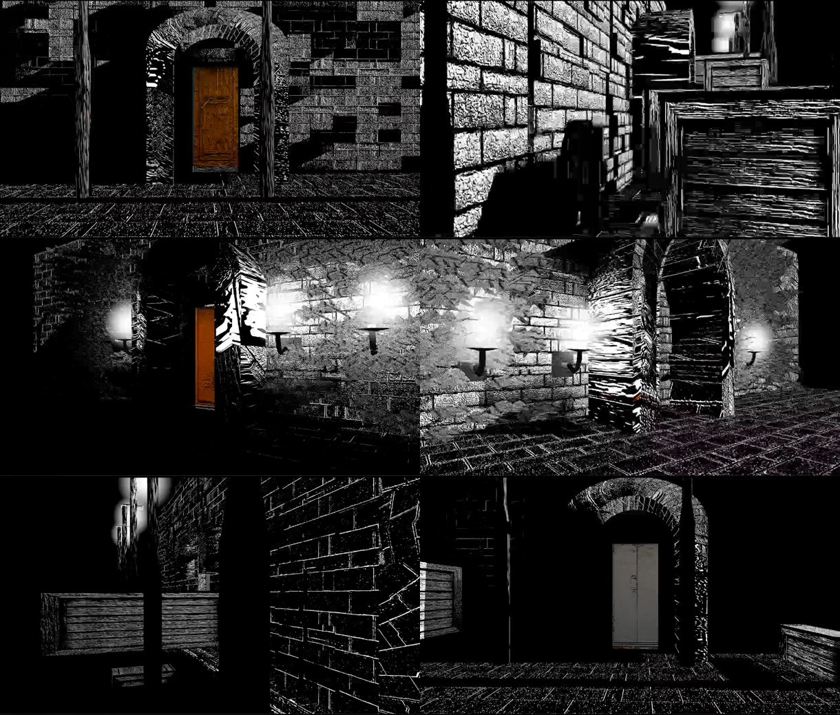
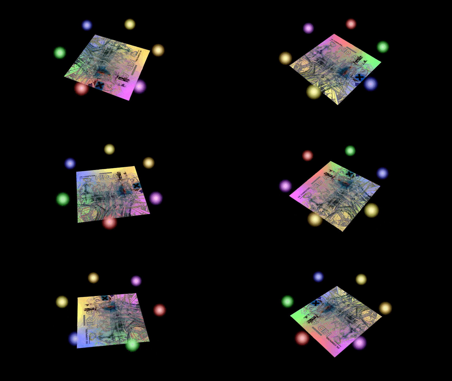
It is possible to keyframe each face within a model separately with some particular attributes. At the beginning of the program, we upload all the keyframes to an array storage buffer on the GPU side. We then index into this based on gl_PrimitiveID (the face we are on), and a push constant offset to point us to the right model. We can change saturation, contrast, the texture map offset and the material. That way, we can have different materials per object, as well as creating the fast moving per-frame texture coordinate offset as showed off in the top of this page. It make everything look a bit more alive and in motion.
A normal map that differs from the actual image appears to be engraved


We can change these values and pass them to the shader


Point lights
We also have point light sources. These are a kind of model that uniformly emit light in all directions. We accumulate the positions and colours/intensities of each point light that exists every frame. This information is then stored on a buffer that we can access in the shader as before. Then, we iterate through each point light and add on its contribution. Here, we use intensity = 1 / distance^2 to calculate the intensity.
We also employ blinn-phong specular lighting. This kind of lighting also depends on the viewer position, and is calculated using the "half angle" between the direction to the point light and the camera position. We then dot product this with the fragment surface normal, and raise it to an exponent, which changes the apparant "shininess". Shininess is a property we specify in the MTL file for each material. We also have the option to use a specular map as before to make different parts of the surface look shinier.
We also use a separate smaller graphics pipeline to render the point-lights themselves. It doesnt take any vertices but instead is forced to run six times per draw call, and draws 2 triangles, forming a square. We then clip any fragments further than a specified radius, something we can also keyframe on a per point light basis, to make a sphere appear. Given that we don't have a depth buffer here, its important that we render each pointlight in order based on how far away they are in that frame.
Currently, three forms of lighting are implemented. The first is simply "ambient light". Ambient light is simply a 4-value vector that represents RGB, and intensity respectively. Each fragments colour has this value added to it, regardless of the orientation of the fragment. The other is directional light. Currently, there is one main "sun" light source configured, and it can be keyframed using two angles for its direction, and a vec4 colour/intensity as before. Here, we take the dot product of the surface normal with the light direction to determine the intensity of this light. In other words, it is proportional to the cosine of the angle between the normal and light source. The light can be treated as if it is infinitely far away, and doesnt drop off in intensity and all light rays are parallel.


Instancing
Probably the hardest keyframeable property to implement was instancing. Instancing allows you to randomly generate a bunch of models onto a parent object. We do this by binding an instance buffer as well as a vertex buffer. The instance buffer is passed per instance and the vertex buffer is passed per vertex. As before, the instance buffer is also stored on local device memory when each model is created. This means that each draw call will now create multiple instances in parallel rather than just a single model. The instance buffer just contains a sequence of matrices in the form of vec4s (for alignment reasons), that transform the instance onto the parent. Before, we passed the model world matrix via a push constant, but now we do not need to do this since we are passing model matrices in the same way we pass the vertices themselves. The child object is the one with the instance keyframe, which contains a pointer to the parent object.
Usually, for each model on each frame, we grab the keyframe for each frame. Keyframes are structs stored on each model for each type of keyframe. It takes the keyframe for the most recent frame that is less than or equal to the current frame. If it differs from the current keyframed value, the property is updated, and then we perform the draw calls. For instancing, we may need to update the child model even if its keyframe hasnt changed. For example, the parent might have moved, and hence we need to recreate the instances, even if the particular density, randomness factor, or local offsets of the instancing for the child hasn't changed.

Instance keyframes are specified by configuring custom structs

Instances automatically track the parent object even if the instance keyframe itself doesnt change


If no parent object is specified, the object gets a single instance which is just the model transform as before.

Low solidity pushes instances to edges. Remember a square is made from two triangles and produces instances in the middle

Lower randomness
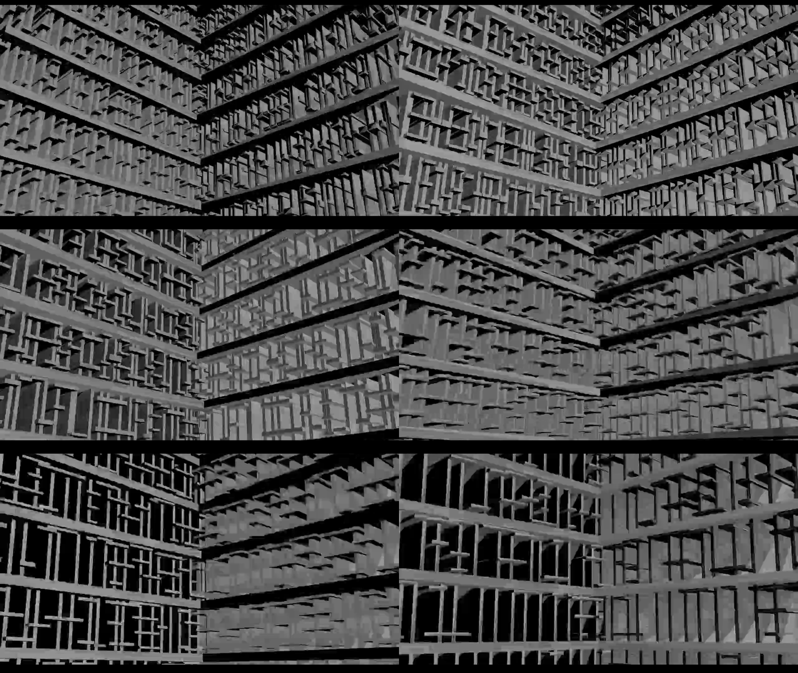
Other than random instances, we can also configure "building instances". This stretches and transforms the child objects in a non-random way such that they form columns and struts over the parent. It does this in the local direction of "up" of the object rather than on every face. This allows us to turn a simple cube into a building without having to create our own model in modelling software like blender, which is what I have done so far. I wont go into detail about every attribute I have added, but in short, I work out the equation of the line across the face, and then spread out a bunch of instances across them. I stretch them out in the parent basis to create parallel columns. I then repeat this for a number of specified layers at currentLayer * layerSeparation height. Then, I create a bunch of "struts", as specified by "strutsPerColumnRange" and stretch them in the opposite axis. This creates the basis of a simple building or scaffolding like structure. We just need to configure the lengths so they exactly match. We need to do this manually because we don't know the exact geometry of the child. I also added a "jengaFactor" which is the probability of randomly removing a strut to give a jenga like appearance, and more flexibility. We can create a fast-moving building with just many instances of a single model. The video below has only one model in the entire scene, and a carefully created instance buffer.

Shadows
We can implement shadows by re-rendering the entire scene again but this time via an orthographic projection. We configure a new pipeline such that it only has a depth attachment. We then render this to an internal frame buffer that isn't displayed. We use an empty fragment shader, since all we need to do is interpolate the depth value which is done automatically, and output that. The position of the view is placed in the direction of the mainLight. Then, we sample this framebuffer in the main shader and remove all light, except ambient light, from the fragment. This process is called "shadow pass", and requires us to setup a new vulkan render pass, imageview, imagememory etc, which we will discuss in more detail later. An orthographic projection is used as this uses parallel lines to define the view volume, much like the light source is assumed to have parallel rays.

This connects numpy 4x4 matrix and glm::mat4
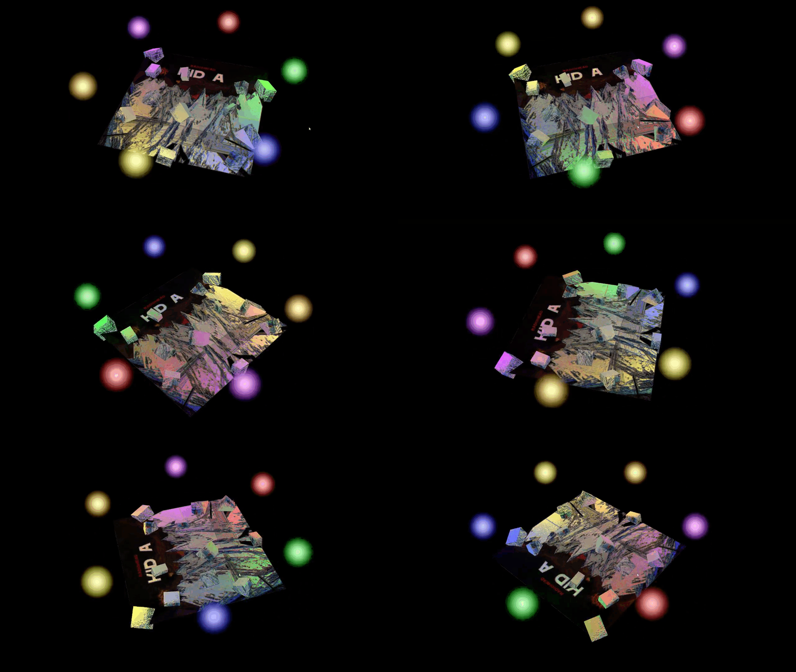
For any random instance keyframe, we do as follows. We first iterate over each face, and extract the relevant vertices. We make sure to transform the vertices by the parents world model matrix. We then take the childs local transform and apply the parents model matrix. This means any local rotations or scales on the child will stay, and also will rotate on the childs local xyz axis, even when it exists on the parent. We then randomly generate a set of uv coordinates. We also have a property called solidity that skews the randomness such that objects appear further on the edges, and a property called randomness that changes the rounding of uv (such that they appear in a more grid like formation for lower randomness). We then similarly perform a linear interpolation calculation on all three vertices with u and v, and add it to the transform. As seen above and to the side, we can successfully instance smaller objects on larger objects. There is also a method called "makeStandAlone()" that can reset the pointer to the parent object back to nullptr, which stops instancing and puts the object back in its local space.

Here a 1x1x1 cube has a building instance keyframe that hasn't been properly configured yet

This scene has only one model and a single material of a single 1x1x1 cube, and we transform each instance with building instances to create this structure.

Empty fragment shader, since all we care about is depth

Python Bindings
So far, all the actual app implementation has been written in C++. We import our models and set our keyframes using a function setScene(), in C++. We can use pybind11 to instead do this in python, for better usability. We just need to bind all the relevant structures and functions, and then setup an embedded interpreter in setScene(), and run a script. The pybind compiles a custom module based on our bindings, which we can import. Pybind seemlessly handles use of pointers (which is good because we reference models with shared pointers throughout).
I have been using GLM for mathematics containers, like vec3s and vec4s. I setup a type casting using PYBIND11_TYPE_CASTER which casts numpy arrays to glm structures (currently I have added support for glm::vec2, vec3, vec4 and glm::mat4, but I may try and make a generalised caster in the future) and vice versa.

Here I'm binding the model class. It is a static member variable, and not done via a constructor (It is tricky to do this with a constructor since we need to move ownership of the model immediately into an std::unordered_map, and then return a pointer). I pass fundamental structures like the device and model map, which are the same for every function call, and so rather than binding these as well, I use a lambda to pass these automatically and then only bind the last 3 arguments, which is much more user friendly.


The python side with custom module. This is similar to bpy or bmesh modules in blender. This code mirrors equivelant C++ code. This doesn't slow down our code, because the python just configures the keyframes, and then the engine actually runs on C++ afterwards.